AFNI version info (afni -ver): Version AFNI_25.0.07 'Severus Alexander'
Hello -
I have seen posts about this issue and tried all the suggestions (e.g., checking s_form and q_form codes, deoblique, checking the orientation), but I still have this issue that the brain mask looks aligned with T1 on AFNI but not on fsleyes. obliquity is 0, and the orientation is LPI, q_form and s_form code is 1, and the q_form matrix and s_form matrix look the same.
My goal is to use the functional ROI made using AFNI on Mrtrix, and I found the images don't look the same between Mrtrix and afni (and this persists on fsleyes and afni).
I would appreciate any further suggestions. In case it is helpful, the files (you can ignore mif files) are available here: DTI - Google Drive
Unfortunately, I don't know about how MRtrix and FSL GUIs work. This is how the datasets look as an underlay/overlay pair in AFNI, is that what you want?
AFNI doesn't care about dset orientation or even whether the grids match between the underlay+overlay datasets---it will place them appropriately based on their (x,y,z) values of voxels. Some other GUI tools seem to do so, either requiring specific orientations only or matching grids. However, these datasets are on the same grids already:
The only difference I might have thought that could exist for the GUI visualizations would be about whether there is obliquity present in the dsets. Different GUIs might decide different tactics to deal with that (either ignore it or resample the data and use it). However, neither dataset appears to have obliquity:
I tried seeing what NIFTI header field differences might exist between the two fields, but I think these are just due to different data type (fine) and size of AFNI extension:
I even tried copying+purging all extensions, but I didn't see a difference in overlaps. (Not that I expected one, given the other outputs, but I thought I would check.)
So, I'm not what is happening in the non-AFNI visualizations.
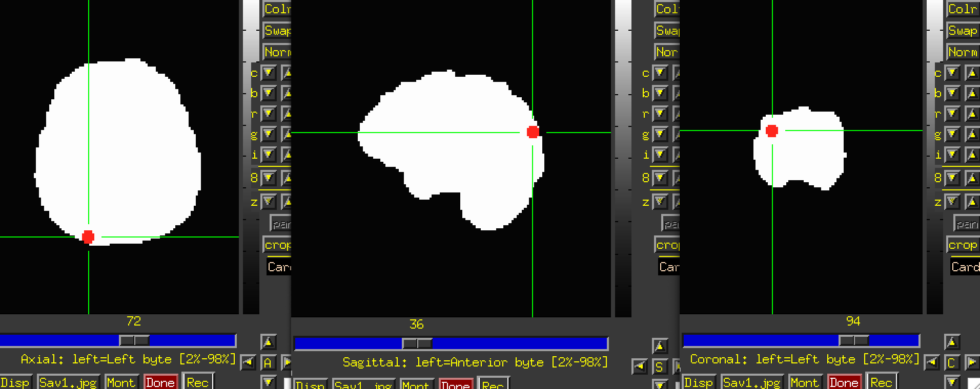
Thanks so much for this! Yeah, on mrview (from mrtrix) and fsleyes, the ROI (red one) is slightly outside of the brain (and misaligned with T1), while it looks perfectly aligned on AFNI.
I also posted this issue on Mrtrix community as I noticed this issue when I converted nii file to mif file using their mrconvert issue. I can see if they have any insight!
This is helpful, still. I might try to register my EPI data to T1 using fsl or ANT function and see if it addresses this issue (I just hate leaving the AFNI world!). Again, thanks so much. Take care!
I don't see what the issue would be from using AFNI for the alignment, esp. since the alignment is where you want it. I would be curious to hear what the Mrtrix folks say.
There are also settings to control the left-right display, the kind of interpolation and the range displays for both afni and fsleyes that can differ between each program.
Oh, that's helpful! Should I then deoblique T1 data and align EPI to the 'deobliqued' T1?
I will try this out (why didn't I think about this possibility!!). Thanks so much!!!
Not related to this — but when I updated afni binaries this time, for some reason, 3dWarp was gone (my version is: Precompiled binary macos_10.12_local: Feb 24 2025 (Version AFNI_25.0.07 'Severus Alexander'). I'm not sure whether I messed up something, but afni_system_checkout did not say anything (other than me not having the r packages).
Oh, I didn't even see that T1w_coreg.nii.gz dset there...
Re. obliquity: as part of FMRI processing with afni_proc.py, we typically recommend deobliquing the anatomical but letting the EPI keep its obliquity. Different software treat obliquity differently, and the anatomical gets processed in different ways (e.g., with FreeSurfer). There are various things "deobliquing" can mean, and we recommend deobliquing the anatomical with adjunct_deob_around_origin, to remove obliquity while keeping the coordinate origin and not regridding. For the EPI, let afni_proc.py deal with it. If you aren't using afni_proc.py, then you have to decide what is best for the software you are using.
Re. package programs: I'm not sure why that program wouldn't be there, but we recommend that people should compile the AFNI binaries locally on macOS nowadays for the installation+updates; the instructions for that are here, depending on whether you have Intel or ARM chip architecture.
Oh, good to know! I will compile the binaries locally then. Thanks!
It was my bad that I didn't make it clear that I'm trying to align it to the T1 data. T1 is already aligned to the DTI data, so in my case, I think I want to keep the obliquity in T1 data in EPI data. Any suggestions on how I can achieve this? When I tried using the 3dWarp -oblique_parent option (and provided T1 data here), EPI data obliquity is still 0. Thanks for your help, again!
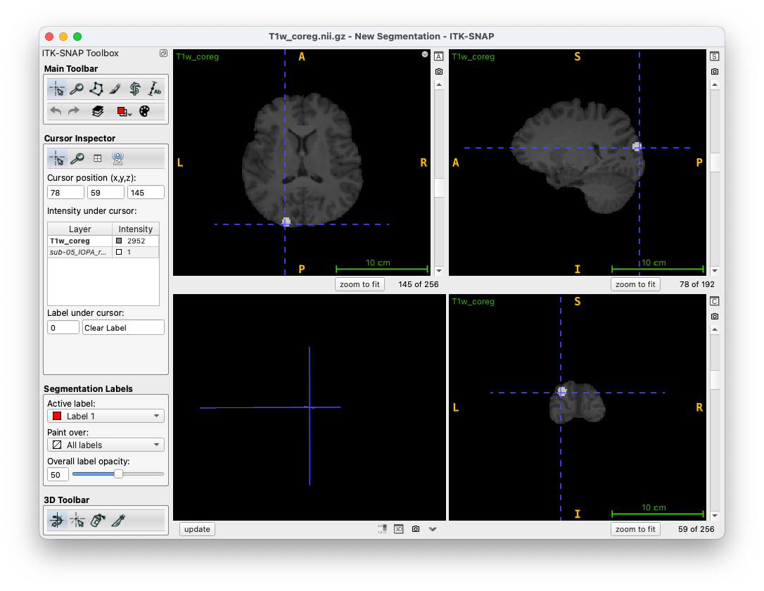
Interestingly everything is also aligned in ITK-SNAP.
When you say that you want to align to the T1 data, you're referring to the T1w_coreg.nii.gz file, correct? In the eyes of AFNI (and ITK) they're already aligned.
Can you give us more information on your diffusion pipeline? That would help me debug.
I agree! I think it is the obliquity issue that you pointed out.
I just want to preserve obliquity from the T1 data in the EPI data. I aligned EPI data to T1 using align_epi_to_anat.py with the deoblique option off, but the epi data still has the obliquity of 0, unlike the T1 data, and 3dWarp -card2Oblique does not change it either. And the output of 3dWarp still looks not aligned with the T1 when I am not using AFNI GUI. I understand that this is not AFNI issue as it looks aligned when using AFNI, but do you have any suggestions? I just want to give the EPI data the same obliquity as the T1 data.
Just zooming out a bit here, is the larger goal to process the T1w dset and EPI together, and to use this spherical ROI in the final output analysis, too? All of these things can be combined relatively straightforwardly in processing command.
Yes. T1w is already aligned to the DTI data, and I am trying to align EPI data to T1 (while keeping the obliquity in the EPI data) and process it to create a functional ROI to use in the DTI analysis (I am using Mrtrix for the DTI analysis).
I tried afni_proc.py and align_epi_to_anat.py, but still can't get the EPI data to preserve the obliquity. Well, at least so far. I will try different options in the preprocessing to get it to work!
Okeydoke, as other folks have mentioned here, I do think this is doable with the programs you mention. If you post what you have started with, my guess is we can help find a solution reasonably speedily. (
I would also ask, why woudl you want to preserve the obliquity in the EPI when it is aligned to the T1? That seems like two different things. I would think you would simply want the EPI well aligned with the T1-in-DTI, to be able to map your ROI to the DTI space. But there might be other considerations, too.
Also, I will note that combining this FMRI-derived ROI with the DTI data makes sense. We have some functionality in the "FATCAT" set of AFNI tools to help facilitate this process, too, like the 3dROIMaker program, which helps keep the mapped ROI close and gap-free to the relevant WM in the diffusion space, as described here.
For now, the preprocessed EPI data (outcome of this command) looks well aligned on T1w, but it has an obliquity of zero (unlike the T1 data).
re: why I want to keep the obliquity in the EPI data — based on what Daniel pointed out above, I am assuming that differences in obliquity between the EPI and the T1 data is the reason why I see the two images well aligned on AFNI viewer but not on mrtrix/fsl visualization programs. I plan to use the mrtrix functions to create streamlines between a functional ROI and some anatomical atlas/regions (different parts of V1), so I want the EPI data and the T1 to look aligned on their viewer.
I am very new to DTI, and I first went over the DTI tutorial from the AFNI workshop, but then I realized that the dataset I am working with does not have the T2 scan (and it seems that the preprocessing pipeline from AFNI requires a T2 scan). So, I started learning the mrtrix preprocessing pipeline and its functions and plan to use their function to perform targeted tractography. I hope this explains my goal/context.
I will check out the 3dROIMaker program! As I am done with the preprocessing part for the DTI data, I guess I can technically move back to AFNI if needed.
Are you wanting to do ROI-based or voxelwise analysis? You have an ROI, but you have also included blurring in your processing. Generally, blurring should not be included in a given ROI-based analysis, because it smears signal across ROI boundaries, artificially increasing correlation among neighboring ROIs (and likely decreasing across distant ones, as signals are polluted by neighbors).
Where did this mask and ROI dsets come from? The mask dset lies on the anatomical (when obliquity is ignored), but the mask has different voxelsize, obliquity and matrix size from the anatomical dset. (The ROI is on the same grid as the mask.)
I want to do an ROI-based analysis. I blurred the EPI data because this is how often people (and I) define scene selective regions. I don't think it matters a lot here, though, because I'm defining this ROI based on the peak coordinate and using a sphere around it.
So, the whole brain mask is something I just created to inspect the misalignment better when I noticed this issue. It is an output from the 3dAutomask of the T1w data but resampled to the EPI data space (but it is not something that is being actually used, so you can probably ignore it...).
The
National Institute of Mental Health (NIMH) is part of the National Institutes of
Health (NIH), a component of the U.S. Department of Health and Human
Services.