AFNI version info (afni -ver): AFNI_24.0.06 'Caracalla'
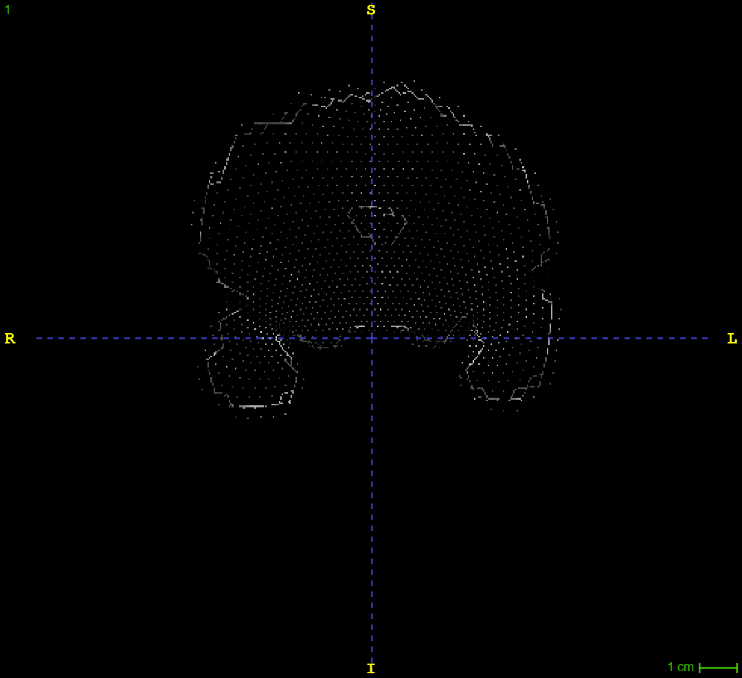
I am running 3dskullstrip on some anisotropic T2w images. I'm having some issues where it removes the first and last coronal slice from the image. Instead, I get a fragmented slice posteriorly, and anteriorly I get what you see in the image provided. The scans are acquired not along the rostrocaudal axis but rather along the long axis of the hippocampus (if that makes any difference). Does someone know how to avoid this issue?
I use -orig_vol because without it the function seemed to mess with the scan resolution, and I tried -push_to_edge to see if that solved the issue (which it didn't).
"$afni_path" -input "$file" -prefix "$output_file" -orig_vol -push_to_edge
Hi-
Hm, OK. I don't think anything about slice ordering of acquisition should affect this.
Is your input dset oblique? What is the output of:
3dinfo -obliquity DSET
?
Secondly, for your input dset DSET_IN and output dset DSET_OUT, what is the result of:
3dinfo -same_all_grid -prefix DSET_IN DSET_OUT
? That will check similarity of 5 different grid properties.
--pt
Hi,
The output from 3dinfo -obliquity DSET is: 23.700
The output from 3dinfo -same_all_grid -prefix DSET_IN DSET_OUT is:
1 1 1 1 0 DSET_IN
1 1 1 1 0 DSET_OUT
/ Gustaf
Hi, Gustaf-
Ah, OK, I think that reveals what is happening: your anatomical dataset has obliquity, and 3dSkullstrip is removing the obliquity. This is something that has been on my "to do" list for a while to change---it shouldn't do that.
We typically recommend deobliquing anatomical data before processing with FMRI (but leaving in the obliquity in EPI data), but this might be a different application. Particularly with visualization of oblique data, there is a tradeoff of ignoring obliquity or of blurring/regridding the data slightly. If you are interested, we have adjunct_deob_around_origin to deoblique in a way that preserves the location of the coordinate origin of the dataset, while not blurring at all.
One way to proceed currently (before I finally do get my act together to update the program---it's a bit complicated because it has several output places, woe is me---is discussed here. Basically:
- Since all the other 4 attributes match, you should be able to "reattach" the obliquity to the output dataset from the input one.
- We will use 3drefit, which will change the header in place, so we start with a copy in case we are unhappy with some result:
3dcopy <dset out> <dset out2>
3drefit \
    -atrcopy <dset in> IJK_TO_DICOM_REAL \
    <dset out2>
- You can verify that things went well with:
3dinfo -same_all_grid -prefix <dset in> <dset out2>
How does that seem?
--pt
Thanks for the valuable information. The application is not fMRI, rather it is manual and automatic segmentation of the hippocampus in anatomical images, which requires preserving the obliquity while not blurring.
I attempted the code provided. However, I'm not sure it works with the setup I have. I usually run loops processing individual scans, and they are in nifti format. So my version of your code is something like:
3dcopy T2_2D_0.4x0.4x1.2mm_180flip_16_ss.nii.gz T2_2D_0.4x0.4x1.2mm_180flip_16_ss_refit.nii.gz
3drefit \
    -atrcopy T2_2D_0.4x0.4x1.2mm_180flip_16.nii.gz IJK_TO_DICOM_REAL \
    T2_2D_0.4x0.4x1.2mm_180flip_16_ss_refit.nii.gz
This generates the following error:
*+ WARNING: Can't find attribute IJK_TO_DICOM_REAL in -atrcopy dataset T2_2D_0.4x0.4x1.2mm_180flip_16.nii.gz
** FATAL ERROR: No options given!?
I see a reference to DICOM in the command, so does it work with nifti format?
OK, then I think what is happening is that original DSET_IN doesn't have the IJK_TO_DICOM_REAL that AFNI would put in its header, because it wasn't created by AFNI. It's OK that it's NIFTI, it just should pass through AFNI to get that attribute calculated.
So, let's just copy the original (that will keep its obliquity), so that it gets populated:
# get unsullied input, with AFNI header extension
3dcopy <dset in> <dset in2>
# copy sullied output, to edit
3dcopy <dset out> <dset out2>
# de-unsully the out2 dataset (via the copied dset_in2)
3drefit \
    -atrcopy <dset in2> IJK_TO_DICOM_REAL \
    <dset out2>
Howzabout that?
--pt
Hi,
Took a while but I tested your new command and it ran without errors. However, the output file still has the same issues anteriorly and posteriorly.
Output:
++ 3dcopy: AFNI version=AFNI_24.0.06 (Feb  8 2024) [64-bit]
++ 3dcopy: AFNI version=AFNI_24.0.06 (Feb  8 2024) [64-bit]
++ 3drefit: AFNI version=AFNI_24.0.06 (Feb  8 2024) [64-bit]
++ Authored by: RW Cox
++ Processing AFNI dataset T2_2D_0.4x0.4x1.2mm_180flip_16_ss_refit.nii.gz
 + atrcopy
++ applying attributes
 + loading and re-writing dataset T2_2D_0.4x0.4x1.2mm_180flip_16_ss_refit.nii.gz (PATH-TO-FILE/T2_2D_0.4x0.4x1.2mm_180flip_16_ss_refit.nii.gz in NIFTI storage)
++ 3drefit processed 1 datasets
Howdy-
I'm not really sure what is being shown here.
What is the output of:
3dinfo -same_all_grid -prefix <dset in> <dset out2>
? Do these show that the grids match?
--pt
I gave you the most anterior and most posterior slice of the <dset_out2> file, as well as the output from the terminal when running the command.
Running 3dinfo, it seems to align:
d -prefix T2_2D_0.4x0.4x1.2mm_180flip_16.nii.gz T2_2D_0.4x0.4x1.2mm_180flip_16_ss_refit.nii.gz
1 1 1 1 1 T2_2D_0.4x0.4x1.2mm_180flip_16.nii.gz
1 1 1 1 1 T2_2D_0.4x0.4x1.2mm_180flip_16_ss_refit.nii.gz
I guess I'm not understanding what the lefthand slice image is. It looks like a mesh/node image. Is the point that that is actually a real, 3D rendering of what should be a "normal" looking slice? Can you show an image using the AFNI GUI, perhaps?
And could you post the three images of what this looks like:
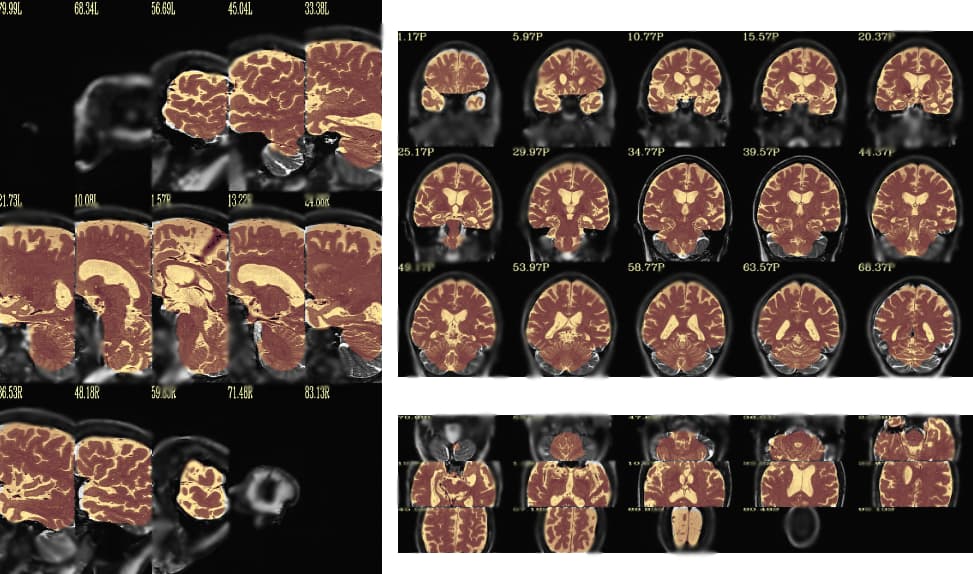
@chauffeur_afni                                                       \
    -ulay         <dset_in>                                      \
    -olay         <dset_out2>                                    \
    -opacity      4                                                   \
    -prefix       image_overlap                                           \
    -set_xhairs   OFF                                                 \
    -montx 5 -monty 3                                                 \
    -label_mode 1 -label_size 4
?
thanks,
pt
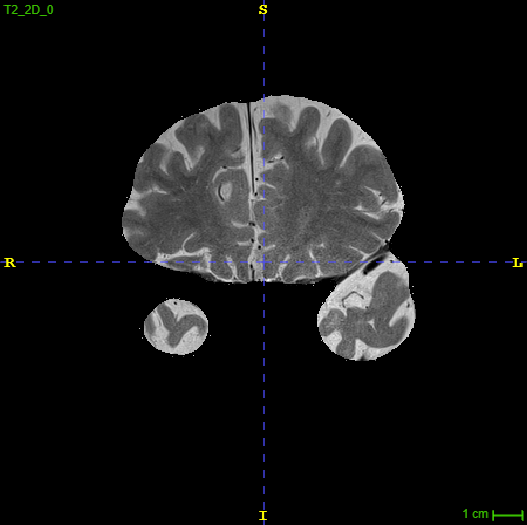
Yes, this is supposed to be a normal looking slice viewed in ITK-SNAP.
I'm a bit unsure about sharing the overlapping images generated since they include the skull (where the very purpose of running the script is to de-skull the images for data sharing purposes). But the overlap loops good, I don't see an issue with the overlap.
To reiterate what I mentioned in my initial message, the scans are acquired perpendicular to the long axis of the hippocampus, in case that angle shift makes any difference in how it's treated by AFNI. They are also scans with in-plane coronal resolution 0.4x0.4mm but slice thickness ranging from 1.2mm - 2.6mm.
Example of the second to last anterior slice (right before the weird one):
I'm trying to get a sense of the before and after data. I don't understand the images you were sending, and it would help me to see the images from the @chauffeur_afni command I sent. As I understand it, that should show the input image (with skull) as underlay, and the output image (with attempt at removing skull) as the overlap.
I don't see why the slice acquisition ordering should matter at all.
Note that having very anisotropic voxels might be a bit of an issue in some things. But showing images will help.
thanks,
pt
I blurred the image in the skull-portion, but hope this suffice.
To illustrate the issue from another angle, here is the problem from a sagittal view. This slice is almost completely removed (the slice described as a mesh/node before).
Hi-
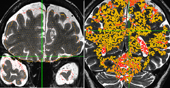
Seeing the chauffeur output helps a lot. The blurring or the secondary image making makes it a bit hard to see what is happening in the overlay.
In this latter image, I think I can see what is happening. Is the issue that the output grid exists everywhere, but in one of the edge-most slices, the data looks to be incomplete, and only sparsely populated with values?
When I look at the AFNI output image with chauffeur, I am not seeing that. Do you see that if you open in the image in AFNI and go to that slice? It is tricky because it is right at the edge. The blurring in the chauffeur images means I cannot tell.
--pt
Yes, that is exactly right. The most anterior and posterior slice is incomplete (sparsely populated with values). I managed to open it in the AFNI gui, and it looks the same.
OK, good to know, thanks. That is what I was wondering---is it a visualization thing, or in the data. This shows it is in the data.
Hmm, I guess is that this occurs because it is really at the boundary of the dataset itself. I have three suggestions to try, in no particular order:
- Zeropad the dataset before running 3dSkullStrip, so the brain isn't at the dataset edge. The following adds 5 slices of zeros at the anterior and posterior part of the dataset:
3dZeropad \
     -A 5 \
     -P 5  \
     -prefix DSET_ZP.nii.gz \
     DSET_IN
- Add some blurring during the processing. This might help reduce some edge features:
3dSkullStrip \
  -blur_fwhm 2 \
  -input "$file"  -prefix "$output_file" -orig_vol -push_to_edge
- Combine both recommendations 1 and 2.
I'm sorry to not have a direct solution out of the box. I haven't seen this kind of weird edge effect before. It is possible some of this results from the algorithm being confused by working on a T2w dataset, since 3dSkullstrip was written for T1w ones. But it seems to be doing a mostly good job elsewhere, hopefully we can sort out the boundary issue. I'm guessing it mostly relates to having the edge of the FOV right there, given where it occurs.
--pt